
Electrical (WIP)
Overview
Welcome to the Electrical Onboarding for the 2025-2026 school year!
Goals
- Learning
- What is a PCB (Printed Circuit Board)?
- What is a Schematic?
- How do you read a Schematic?
- Practical
- Soldering components on a PCB
- Debugging/Testing a PCB
Reading a Schematic
You can find the schematic for the PCB you will be working on here. The first three pages contain the actual schematic for the PCB, although you can mainly ignore the first page as it is purely for connections across sheets. A schematic is just a logical and visual representation of the PCB. The third (last) page of the pdf contains a top down view of the board with all of its layers.
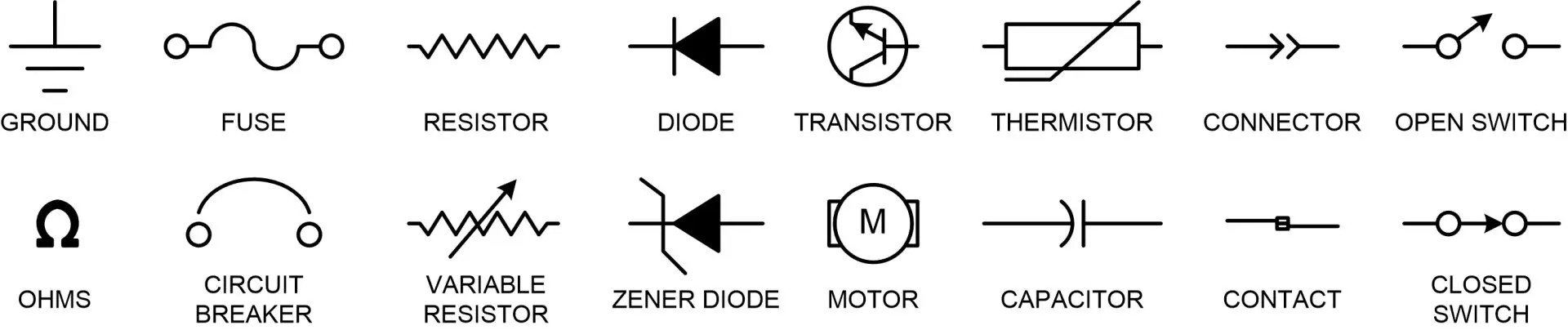
The schematic is full of symbols like some of the ones seen below.
You may also noticed that next to each symbol or component there is a designator, like SW1 shown in the image below. These correspond 1-to-1 on what you will see physically, as also shown below.


Understanding the Board
After taking a look at the schematic, you may have noticed there are quite a few components spread throughout the board. What do all of these do? How do they work? How do they connect?
Voltage Regulation
In order to actually power your robot, you will be using a battery holder that takes four AA batteries. With each battery at 1.5 volts connected in series (chained together), our max voltage we will have to deal with is around 6.0 volts. While this is great for some applications, the line sensors and Pico operate on 3.3 volts. To solve this, we can use something called an LDO which is found at designator U1. This will create a stable 3.3 volts from our unstable battery voltage. In our case, we only need this to power the Pico and then we use the 3.3 volt output on the pico to power everything else (explained later).
At designator D1 you'll find a diode. This essentially ensures that power can only flow one direction, in the case of this diode it only flows towards the direction of the silver band (indicated in the picture below). The reason the board requires this is because when you have your computer plugged into the Pico (which provides power across the VBUS line), you don't it back flowing (need proper word check) into your computer.
Raspberry PI Pico
The Raspberry PI Pico is our chosen microcontroller for this project. A microcontroller is more or less just a tiny computer that is used to interface with hardware components like motors, servos, sensors, etc. You will be given a presoldered pico for your robot.
Line Sensors and Servos
Both of these are fortunately pretty simple. The Line Sensors are powered via 3.3v from the Pico and have their data lines connected directly to the Pico as well. These are simply read in firmware by checking whether the signal is Low or High. The servos are powered straight from the battery and are driven directly off of the Pico.
Motor Driver
In order to control the motors in a safe and reliable way, we will make use of a Motor Driver. This small IC (Integrated Circuit) found at designator IC1 takes the control signals that the PICO produces and converts them to the power needed to drive the motors. Other than some capacitors nearby per the datasheet, there isn't much else here!
LEDs
The LEDs are pretty basic, you connect power and ground and they light up. Most importantly, you will see that there is a resistor before each LED. The purpose of these is to limit the flow of current into the LEDs which helps prevent burnout or any issues. They are polarized, which the long leg of the LED indicating the positive side, which is also indicated on the board.
Capacitors
You may notice that the one component we haven't covered yet is all of the capacitors, designated by Cx, spread throughout the board. There are three different capacitors on the board: 0.1uF, 10uF, and 100uF. All three of these serve different purposes
- 0.1uF: These serve as decoupling capacitors, a way to smooth out high frequency noise in power. You will see this scattered everywhere on a lot of the boards built in SCR (and in industry).
- 10uf: These serve a similar purpose to the 0.1uF mentioned above, but is requested in the datasheet of the motor driver.
- 100uF: These are found near components that may have sudden "bursts" of power draw, namely the motor driver and the servo.
Soldering Basics
Before we get to assembling, lets walk through a few rules and tips about soldering. But first, what is soldering? Soldering is a method to permanently attach a component to something like a printed circuit board. Typically, as shown in the graphic below, you use solder (a metal alloy) and melt it to create that connection.

Step 1: Tinning
This is a step that helps protect the tip of the soldering iron and can help in general use of transferring solder to the component/board. Start by letting the soldering iron heat up, clean the tip with the provided sponge, and then press some of the solder on the tip and let it flow for a moment. It doesn't need a lot, just enough for the tip to turn a similar color to the solder.

Step 2: Soldering
Well, there are only two steps here but this is a really big step. Lets start by mounting the component that you want to solder to the board. On the top side, place it through the board in the correct orientation (if you are confused here please ask a mentor) and bend the legs such that it won't fall out when you tip the board over.

Next, lets heat up the pad of the area you want to solder. The pad is just the small metal circle (or square), known as a solder joint, that surrounds the hole.

Finally, lets apply some solder to that pad. Continue holding the soldering iron on that solder joint and touch your solder onto it at the same time. Try not to touch the solder directly to the tip of the iron at this point, the solder joint should be hot enough to melt the solder.

]
You should end up with something that looks more or less like this! We will also try to wander around and verify your first solder to make sure you are on track!

]
Rules
- Do not touch yourself or any other person with the metal tip of the soldering iron at any time. These irons get extremely hot and will cause harm.
- Whenever you finish with a soldering iron, be sure to clean and retin the tip!
PCB Assembly
Now that you have learned some of the basics on how to solder and what all of the components do, its time to start assembling! For all of those in your team that wishes to solder, you should try breaking up the components so that each person gets to solder one of each component as practice! You may not be able to finish your entire PCB
Don't be afraid to ask for help!
Soldering for the first time can be a scary process, but we are here to help you! If you and your team do not feel comfortable soldering your board, that is perfectly fine as well!Most importantly, if you get burned in any way immediately inform one of the officers so we can assist you as needed.
Testing
Now it is time to test your PCB! If there is enough time for this, contact one of the mentors and we will walk through the testing steps. If there isn't enough time, we will manually test your PCB to ensure all of the individual components work. We will test your PCB regardless of whether we got to test it in the session just to double check :)