
Week 1 - Electrical / Software
Overview
Welcome to the Electrical & Software Onboarding for the 2026-2027 school year!
Goals
-
Learning
-
What is a Schematic / How to read a Schematic
-
How does a microcontroller control hardware?
-
-
Practical
-
Breadboarding a circuit
-
Running and debugging Arduino/ C++ code
-
Managing software dependencies and reading software documentation
-
Circuit Breadboarding
Reading a Circuit Schematic:
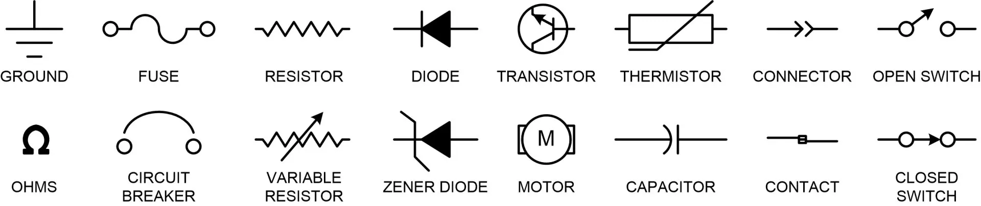
A schematic is just a logical and visual representation of the circuit. Below are a bunch of circuit symbols you may see on your schematic:
The schematic you'll be using to construct the project is found below:
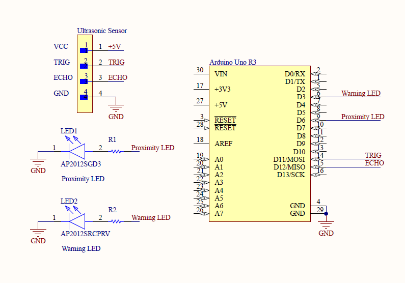
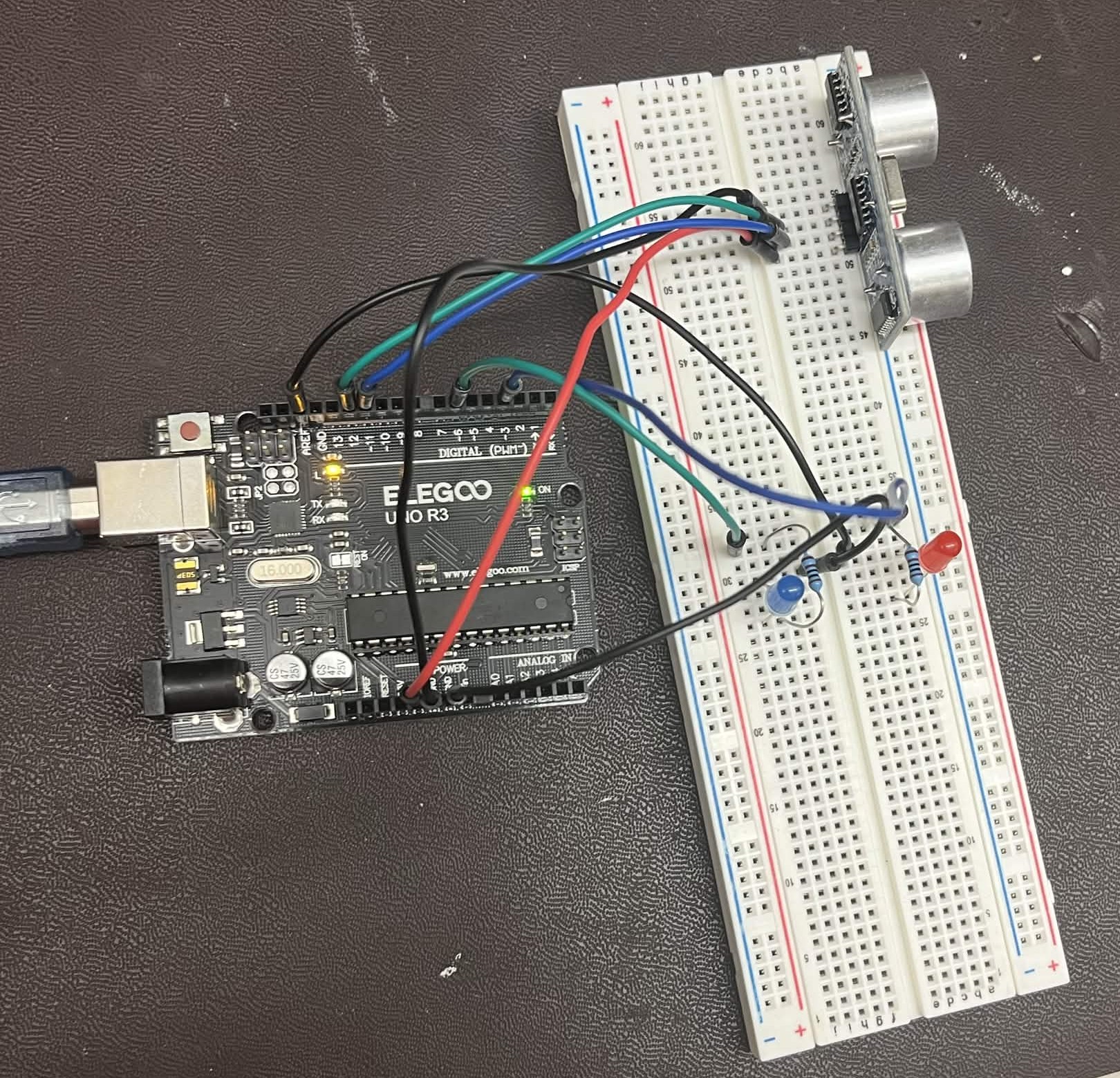
Use the schematic to construct the circuit on your breadboard. Once completed, you should have something similar to below:
Once you have your circuit constructed, you're now ready to install and upload your project's firmware.
Downloads
Arduino:
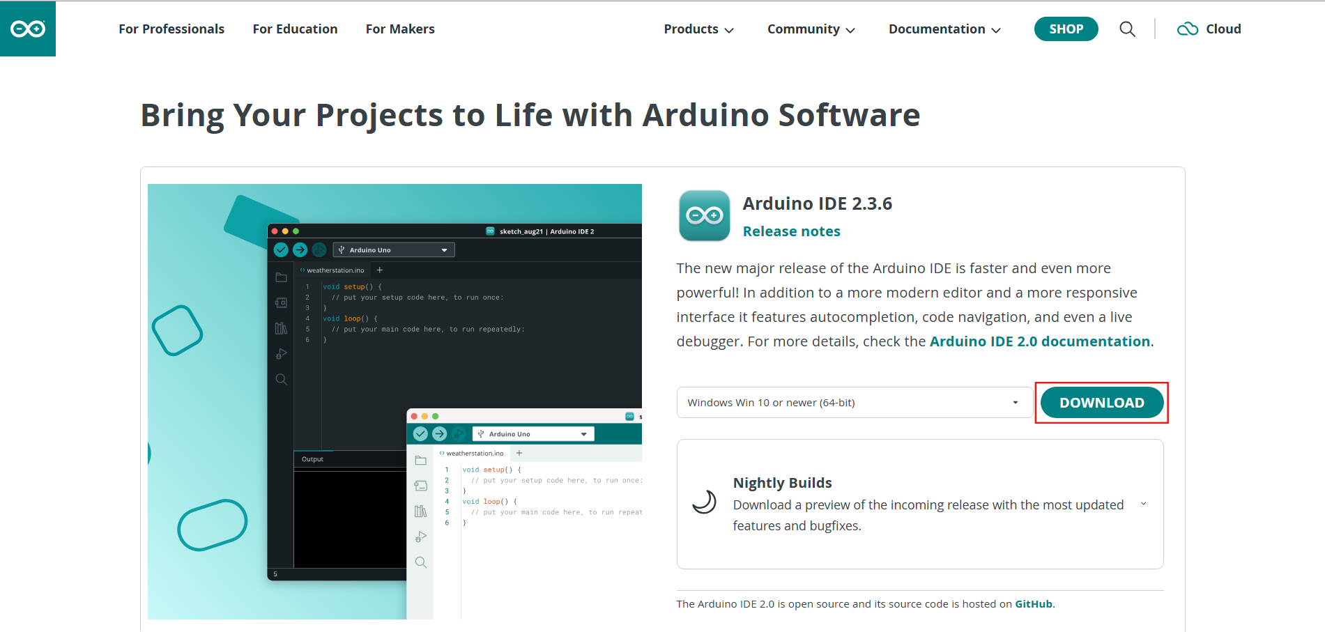
Go here and download the version of the arduino IDE for your operating system (Windows, OSX, linux).
Pico board support:
We'll be using the Elegoo Uno R3 for onboarding. To develop on the uno, you need to add an additional board manager URL to the Arduino IDE.
Go here and scroll to the installation section. Follow the short directions there.
In the boards manager tab, search for these two libraries and install them
Compilation
Open Arduino IDE:
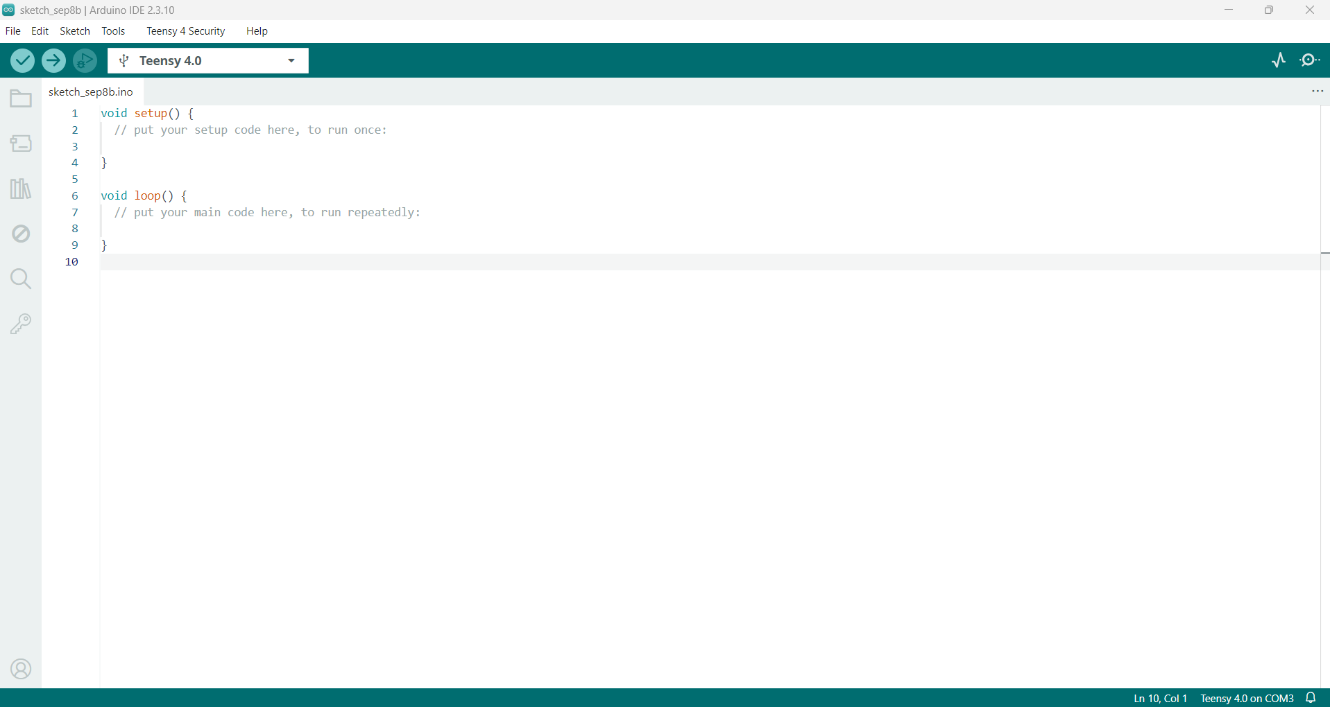
Open the Arduino IDE application. If you have the correct application downloaded, you should see this window.
Select the Uno R3:
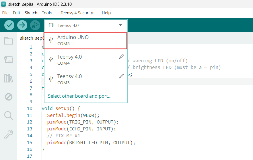
Connect the Uno R3 to your computer using a micro-usb cable. On the top left, you should see the option Arduino UNO appear in the drop down dialog.
Verifying Source Code:
Copy this skeleton code into an arduino sketch file:
const int TRIG_PIN = 11;
const int ECHO_PIN = 12;
const int LED_PIN = 3;        // warning LED (on/off)
const int BRIGHT_LED_PIN = 6; // brightness LED (must be a ~ pin)
const int DISTANCE_THRESHOLD = 5;

float duration_us, distance_cm;
int brightness;

void setup() {
  Serial.begin(9600);
  pinMode(TRIG_PIN, OUTPUT);
  pinMode(ECHO_PIN, INPUT);
  // FIX ME #1
  pinMode(BRIGHT_LED_PIN, OUTPUT);
}

void loop() {
  // generate 10-microsecond pulse to TRIG pin
  digitalWrite(TRIG_PIN, HIGH);
  delayMicroseconds(10);
  digitalWrite(TRIG_PIN, LOW);

  // measure duration of pulse from ECHO pin
  duration_us = pulseIn(ECHO_PIN, HIGH);
  distance_cm = 0.017 * duration_us;

  // warning LED
  if (distance_cm < DISTANCE_THRESHOLD)
    digitalWrite(LED_PIN, HIGH);
  else
    digitalWrite(LED_PIN, LOW);

  // brightness LED — gets brighter as object gets closer
 brightness = map(distance_cm, 2, 30, 255, 0);
 brightness = constrain(brightness, 0, 255);
  analogWrite(BRIGHT_LED_PIN, brightness);

  Serial.print("distance: ");
  Serial.print(distance_cm);
  Serial.print(" cm  |  brightness: ");
  Serial.println(brightness);

  delay(500);
}
This file contains const declarations
Edit the setup() function and replace line 14 with the following:
pinMode(LED_PIN, OUTPUT);
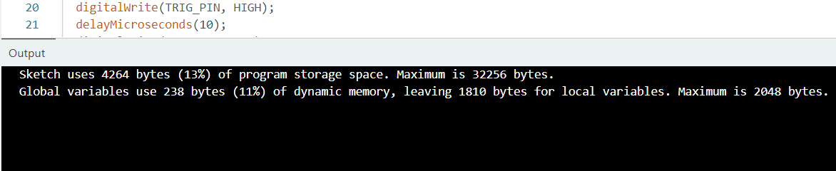
Click the check mark at the top left of the IDE to check for compilation errors. If your program compiles correctly you should see this output.
Uploading Program to Uno R3:
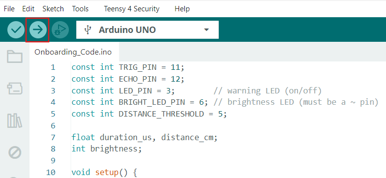
Click the arrow at the top left of the IDE to flash the Uno R3. If flashing doesn't work, you may need to unplug the Uno R3 and hold the Reset button on the Uno R3 (the red button) while reconnecting the micro-usb cable.
If your upload is successful, your proximity LED should turn on once you wave in front of the ultrasonic sensor.