
Week 2 - Mechanical
Overview
In this onboarding, you will make an Onshape account and get added to the SCR Onshape, along with learning the basics of CAD.
Goals
- Creating an Onshape account and getting added to the SCR Onshape
- Practical
- How to draw a sketch
- How to use extrude to create a basic part
- How to use linear pattern to make many features at once
- How to mate parts together in an assembly
Don't be afraid to ask for help!
If you are having trouble during this session, that is okay! We don't expect you to get everything perfect during your first attempt. Our officers are here to assist you.
What is MCAD?
Computer-Aided Design (CAD) is the use of various programs and tools on a computer to assist engineers with design. Mechanical CAD (MCAD) refers specifically to tools for mechanical design, although it is common for MCAD to just be referred to as CAD. The most common application of MCAD is 3D design of parts and assemblies.
Part Design
Part design involves creating 3D objects. The workflow for creating a part is below:
- Create a sketch
- The sketch is often a cross-section of the part you are creating
- Draw the geometry with various tools such as lines, rectangles, circles, etc.
- Define the dimensions of the geometry using the dimension tool
- Bring your sketch into the third dimension with tools such as extrude, revolve, etc
Creating an Onshape Account
Onshape is an online browser-based MCAD program, so no download is needed. If you already have an Onshape account, feel free to skip to "Getting added to the SCR Onshape". To create your Onshape account, go to this link:
https://www.onshape.com/en/sign-up
Steps to Create Account
- Enter your school email
- Select education
- Select student and college
- Select the student plan (should be the only option on screen)
- There will be some information to enter after selecting your plan. Enter the following:
- University of Oklahoma (OK-USA)
- ou.edu
- Graduation year
- Major
I will be using Onshape for design work on a competitive robotics team.
Getting added to the SCR Onshape
Send your Onshape email to onboarding-2026 in the Discord. We will add you to Onshape, and you should get an email with the invitation.
OnShape Introduction
Congrats! You now have an Onshape account and have been added to the SCR Onshape! You should see a screen similar to this.
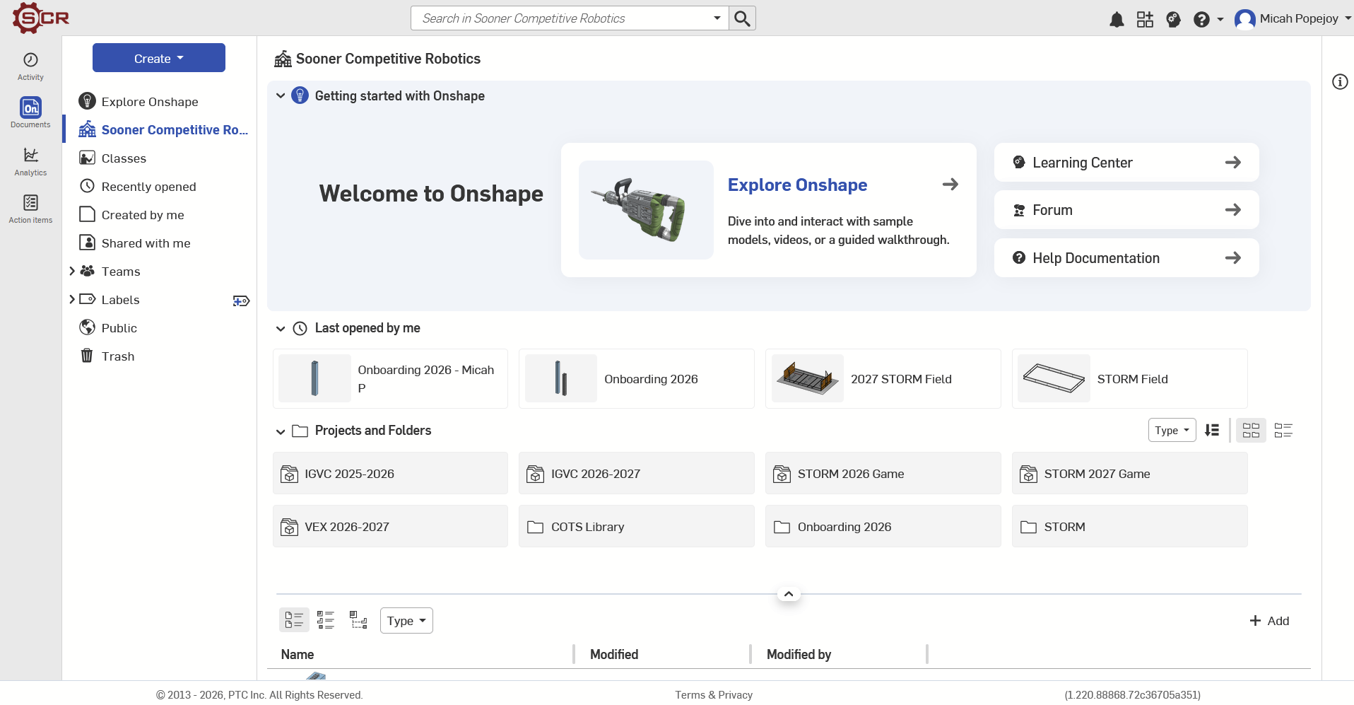
Select the "Aluminum Tube" assignment and start the assignment.
Navigation Basics
You should see the empty workspace below. Some basics parts of your
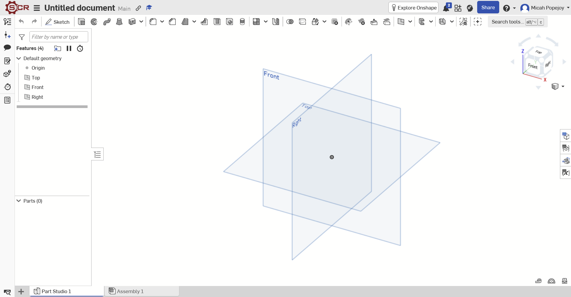
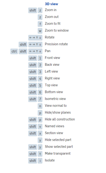
ImportantAluminum TopicsTube
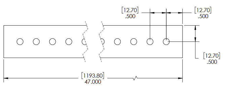
The main project you will be working on is a piece of aluminum extrusion. This is a very simple piece, and is something that is commenly encounted for robot structures.
Part Studio
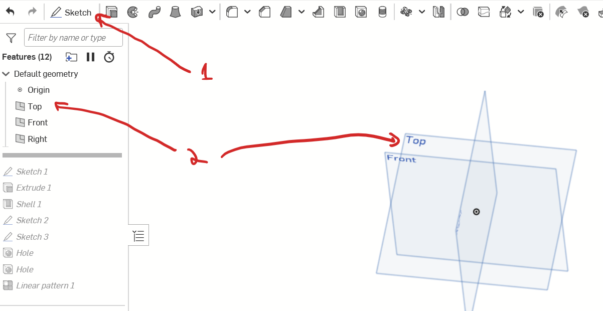
Start out with creating a sketch on the top plane. Do this by clicking Sketch in the top left, and then clicking on the plane named top.
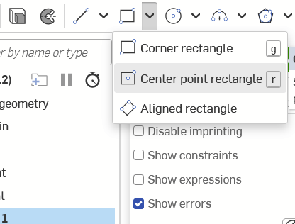
Create a center point rectangle. Do this by clicking on center point rectangle in the top left, and then clicking on the origin (the black and white dot in the workspace) to position it.
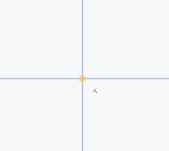
Then just drag out and click to create a rectangle.
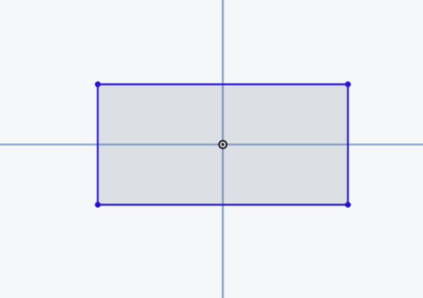
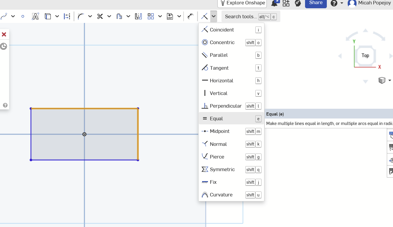
Now, let's turn this rectangle into a square! Click on the perpendicular edges of the rectangle, and click on the drop-down constraints menu in the top right, and select equal. Constraints are an important part of sketches, and in this case, ensure that this shape is always a square no matter its dimensions.
Next, click the dimension tool (or d on your keyboard). The dimension tool is among the most important tools for sketches and allows you to define the size of your part. Click on one of the edges of the square, click again to set the dimension, and set it to 1 inch. You can double-click on the dimension to edit it.

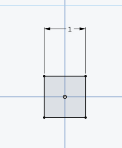
Next, we will bring this into the third dimension! Go ahead and click on the check mark in the sketch window to close the sketch.
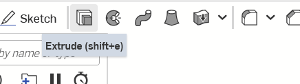
Now that you have exited the sketch, click on Extrude in the top left. Then click on your sketch, and type in a length of 8 inches.
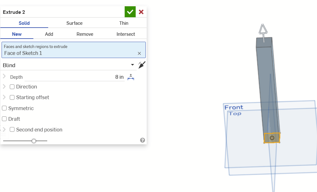
Now you have a 3D part!
Next, we need to hollow out the tube. We will do this with a special tool called the shell tool.

Click on the two square faces of the tube, and set the thickness to 0.125 inches (you can also type 1/8, and onshape will do the math for you).
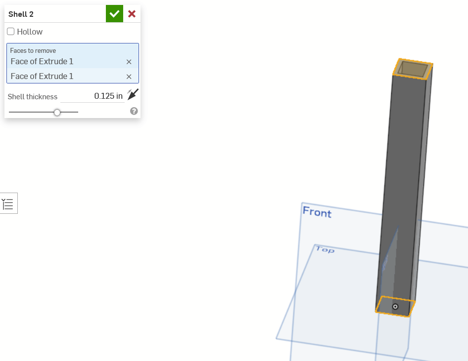
Next, we are going to create the holes. We will do this by first creating the base holes, and then making a pattern of it.
First, create a sketch on one of the faces of the tube, and place a point in the center of the tube, offset by 0.5 inches from the end. We can keep the point in the center by creating a vertical constraint between the origin and the point.
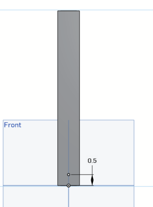
Next, exit the sketch and click on the hole tool. Then click on the point. The hole setting should match the ones in the picture below. Choosing through all allows you to get two holes for the price of one!
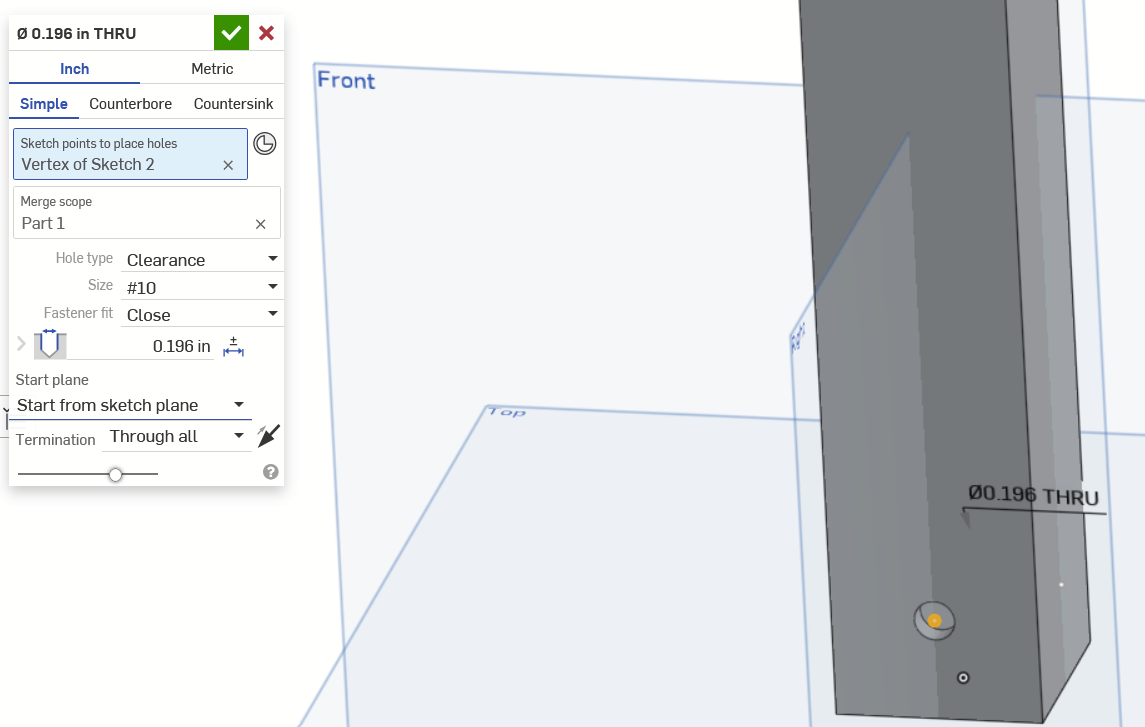
Repeat the above process, but for the perpendicular face of the tube. You should now have 4 holes, one on each side of the tube.
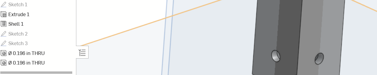
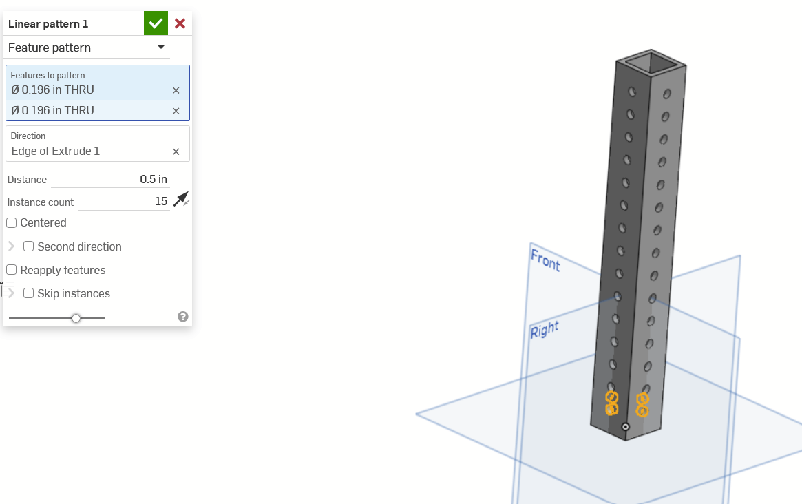
Finally, we will use a linear pattern to repeat the hole all the way up the tube. This allows us to just make the hole once, rather than 15 separate times! Select linear pattern, choose Feature Pattern in the drop-down at the top (Part Pattern is the default and this will NOT work), and then select the two holes you made in the feature tree as your features to pattern. For the direction, choose an edge of the tube that goes the long way. Set the distance to be 0.5 inches, and the instance count to be 15.
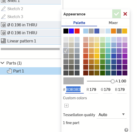
We can also change the color of the model to be more metal-like. Do this by right-clicking Part 1 in the bottom left and selecting Edit Appearance.
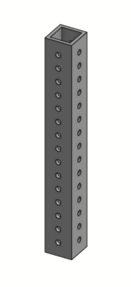
You now have an aluminum tube!
- sketches
- dimensions
- constraints
- construction?
- patterns?
- the "use/project" feature?
- extruding
- revolving too?
- thicken lowkey kinda nice too
- the hole tool is also probably good
- assemblies
- importing from your own part studio
- importing from another part studio
- uploading a file? exporting?
- mating
- probably just a fixed or maybe a revolute, don't really ever need the others