4. Board Layout Pt. II
Before you begin, this tutorial assumes you completed part I of the layout tutorial. You can find the tutorial by accessing this page: 3. Board Layout Pt. I
Component Placement
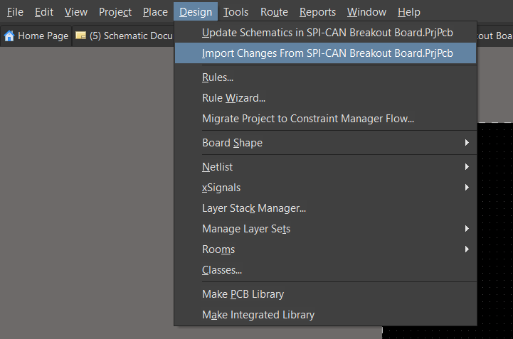
Before you begin,can thisplace tutorialyour assumescomponents, you completedmust partimport Iyour ofparts from the schematic you created. To import your components, navigate to the top left tool-bar, select Design --> then select Import Changes From SPI-CAN Breakout Board.PrjPCb.
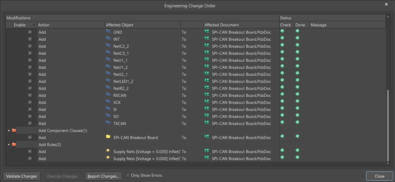
A new window will appear showcasing which componens and nets will be added to the layout.
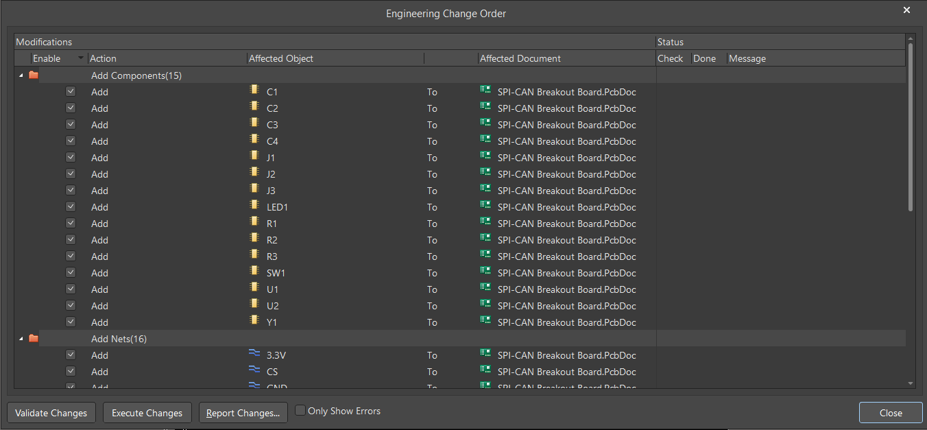
Go ahead and select Validate Changes, then select Execute Changes. Green checkmarks will appear under the Check and Done columns, indicating if a component has been successfully imported.
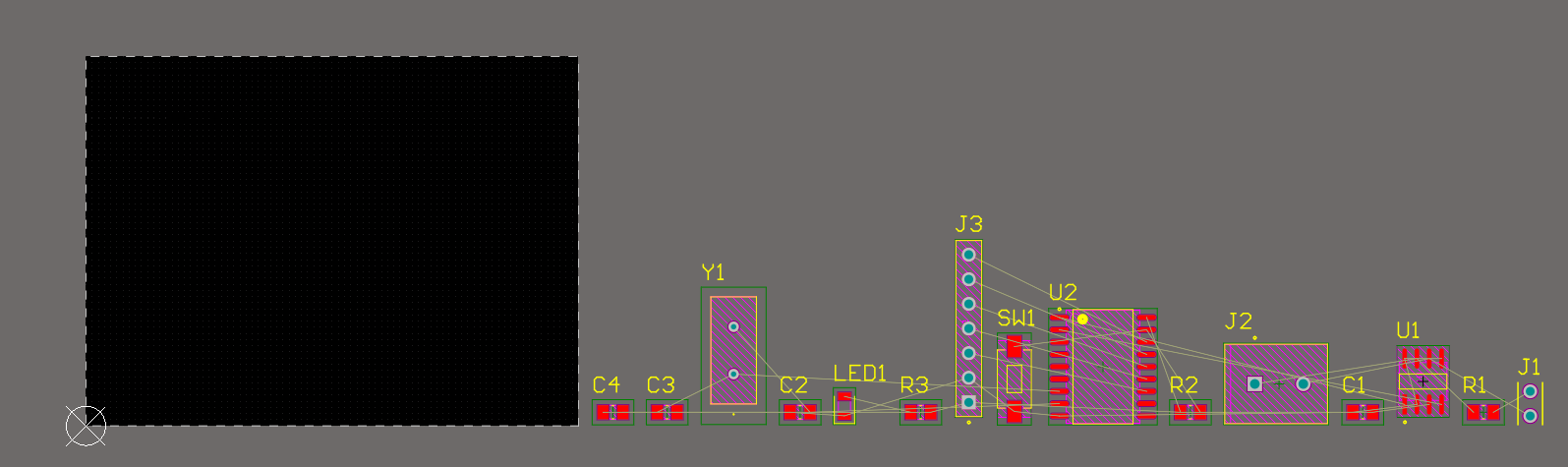
Upon closing the window, your parts will appear on the layout tutorial.as Youshown canbelow:
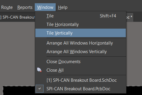
Typically, you can click and drag components into your board dimensions. For the sake of time, we'll use a different technique for placing components by having our schematic and PCB documents open side-by-side.
Start by having only two windows open: your schematic and your PCB documents.

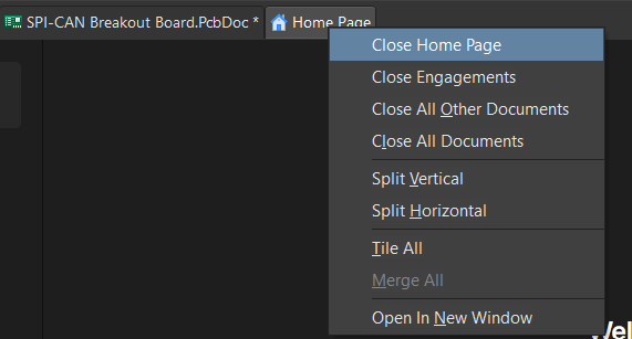
To close a window, right-click on the window you want to close, then select Close [Window Name]