
2. Creating a Schematic
Introduction
Creating a schematic in Altium is one of the most important steps in PCB Design. Before you create a schematic from scratch, you should already have a good idea on what your PCB will be used for, the logic behind the design, and critical components that will allow for a successful design.
During the schematic design process, you'll follow the steps below:
- Requirements - deciding the necessary interfaces, constraints, etc.
- Project Libraries - determining which components are needed for your design.
- Component Arrangement - arranging and wiring the components on your sheet.
- ERC / Compiling - Checking for errors and validating your schematic
Schematic Sheet Set-Up
When you start, you should already have a blank schematic loaded.
- For information on how to create a blank schematic, refer to 1. Project Creation
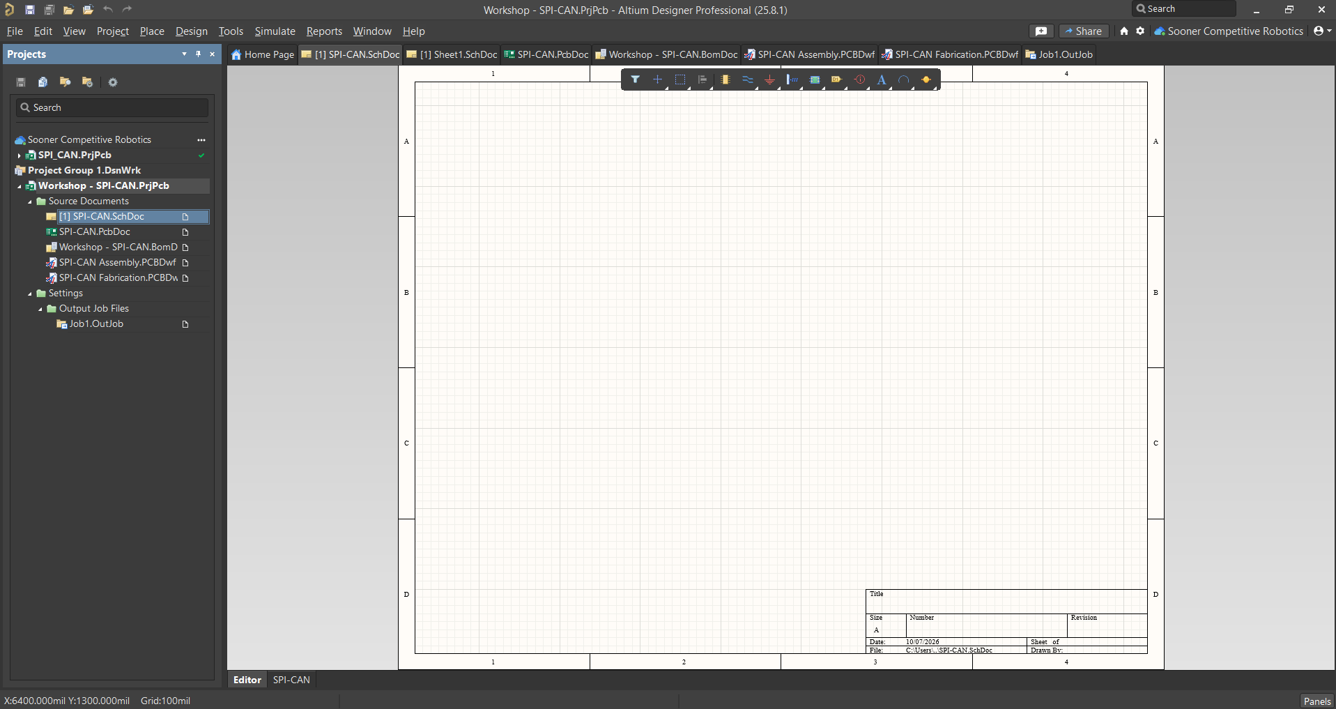
As you're creating your schematic, it's helpful to know these controls:
- Right-Click & Hold: Moves the Page
- Scroll Wheel: Move up and down on the Page
- Ctrl + Scoll Wheel: Zooms in-and-out of the Page
Before designing your circuit schematic, it's important to make sure your sheet has everything set-up properly. This includes the Sheet size, title, author, and more.
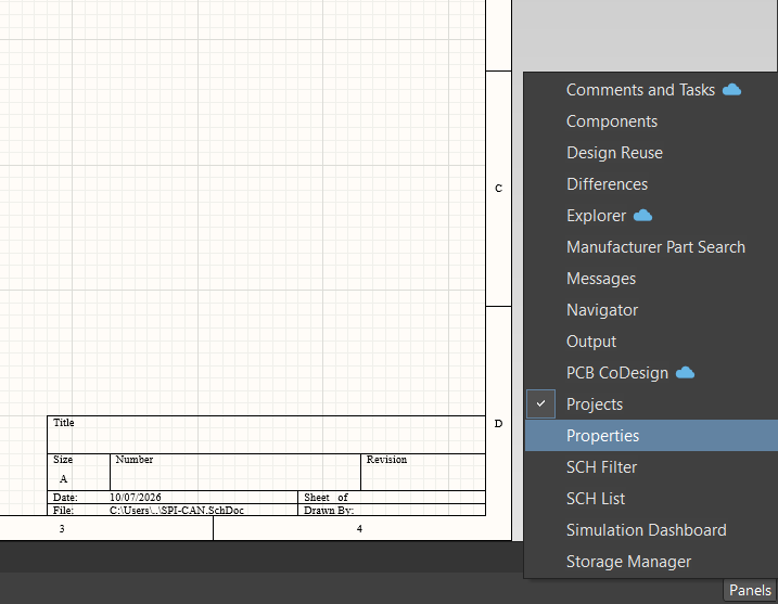
A new window should appear as seen below:
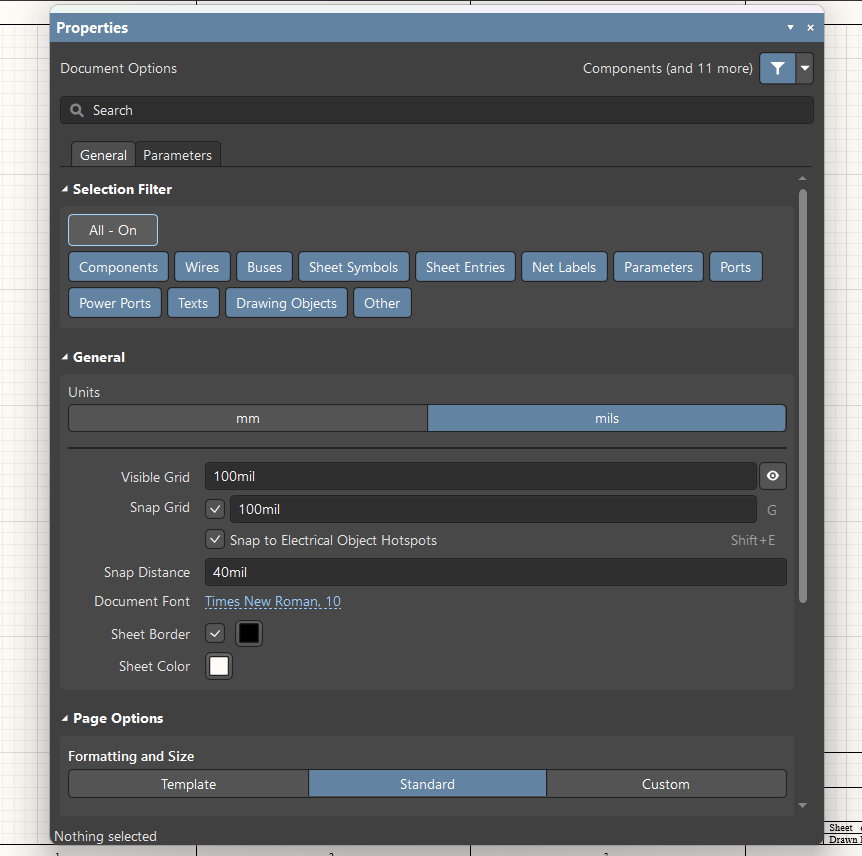
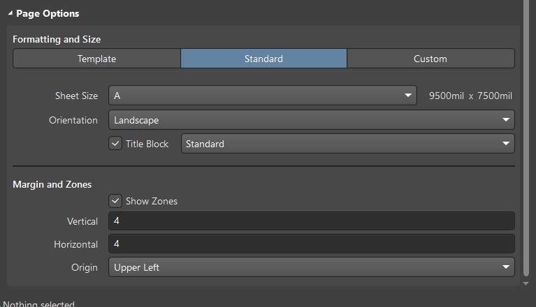
If you scroll down, you can modify the Sheet Size, Orientation, and more! For now, we'll leave the settings as they are.
If you select the Parameters tab (under the Search Bar), you can modify the sheet's elements.
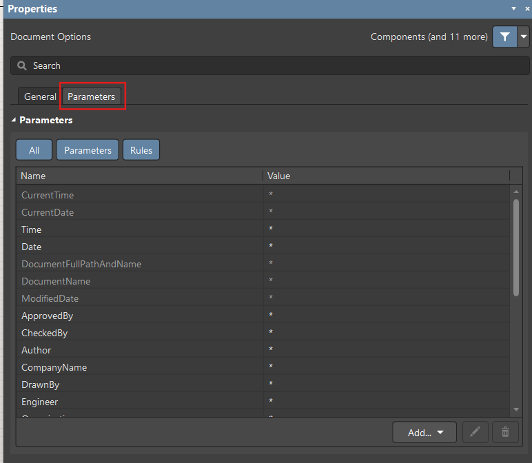
Go ahead and modify the following parameters with the following values:
- Date - Today's Date
- Author - Your Name
- Title - "SPI-CAN Breakout Board"
- Revision - 1
Next, you'll need to place these values on the sheet. With the values set, exit out of the properties window and navigate to the top of the window.
You'll find a tool-bar filled with many icons. Hover over the "A" icon and right-click until a drop-down appears. Then, select Text String.
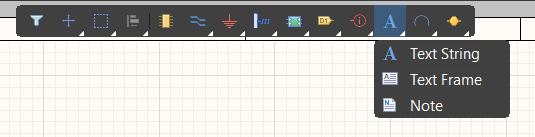
You'll see the word "Text" appear and move along with your cursor. To place it on your dialog box on your schematic, simply left-click on the sheet.

Like all objects placed on a schematic, you can left-click and hold down on an object to move it around. With this in mind, place a bunch of text boxes in the arrangement below
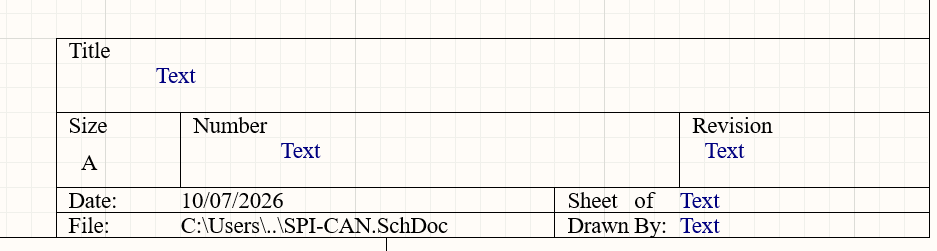
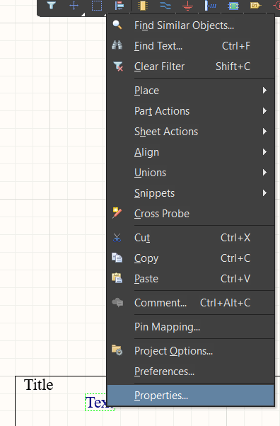
To update the text, right-click on a Text box, then select Properties
Next, in the drop-down arrow in the Text box, navigate to the value you want to atrribute to your text box.
- Note: you can also just type the text directly into the Text box.
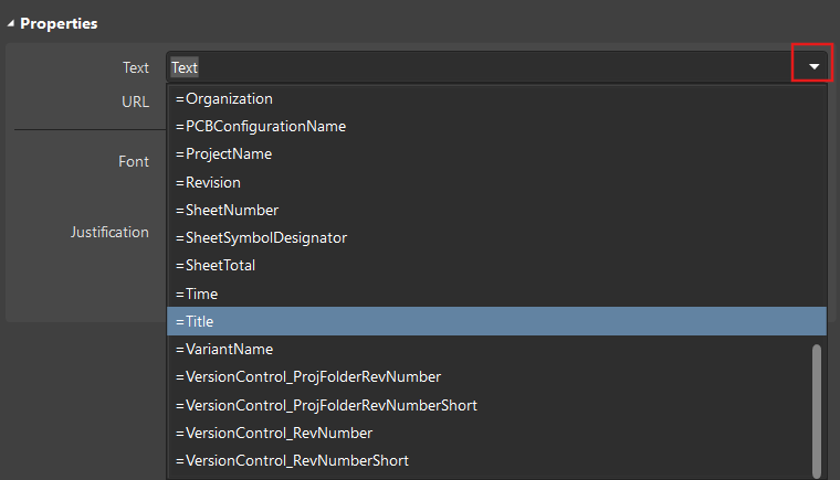
Go ahead and update the text boxes using the procedure above. You can also update the text size and color to your liking.
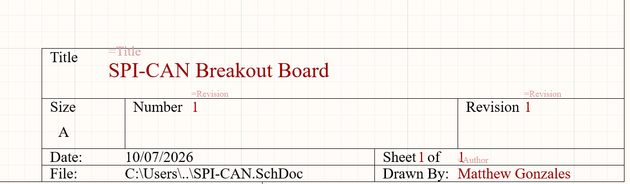
Component Selection & Placement:
You're now ready to begin placing components on your board. Typically, you'll need to conduct proper research on your circuit design beforehand. Fortunately, we have a design ready for you.
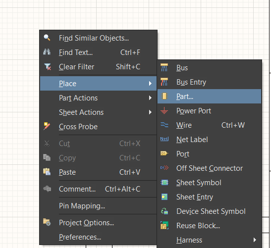
Start by right-clicking anywhere on the schematic. Then, select Place --> select Part
A new window should appear, allowing you to search for parts from the Sooner Competitive Robotics workspace components library. To start, go ahead and insert the text "MCP2515-E/SO" into the Search box.
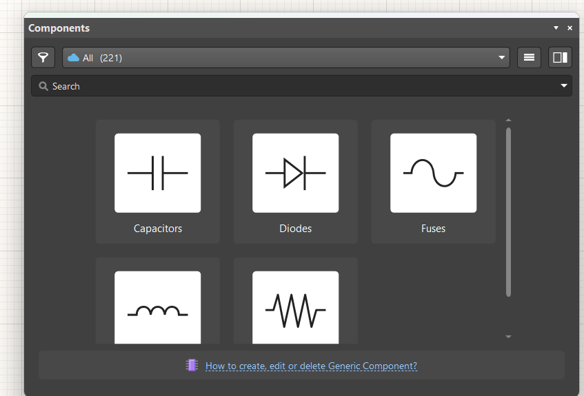
You should see the part you searched up appear below. If your desired component is not saved to SCR's custom parts library, you can always search for parts inthe Manufacturer Part Search.
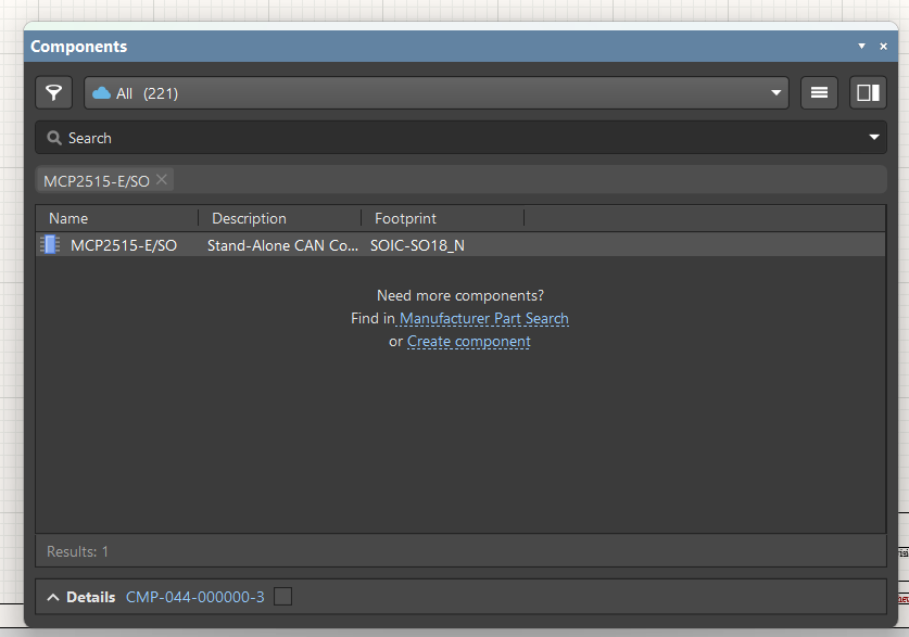
To place your part, double left-click the part's icon. A faded version of your part should appear on your schematic. Left-click on the sheet to place your part. Once you exit out of the Components window, your part should appear on the page like below:
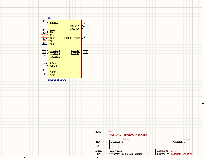
Now, go ahead and place