
2. Creating a Schematic
Introduction
Creating a schematic in Altium is one of the most important steps in PCB Design. Before you create a schematic from scratch, you should already have a good idea on what your PCB will be used for, the logic behind the design, and critical components that will allow for a successful design.
During the schematic design process, you'll follow the steps below:
- Requirements - deciding the necessary interfaces, constraints, etc.
- Project Libraries - determining which components are needed for your design.
- Part Arrangement - arranging and wiring the components on your sheet.
- ERC / Compiling - Checking for errors and validating your schematic
Schematic Sheet Set-Up
When you start, you should already have a blank schematic loaded.
- For information on how to create a blank schematic, refer to 1. Project Creation
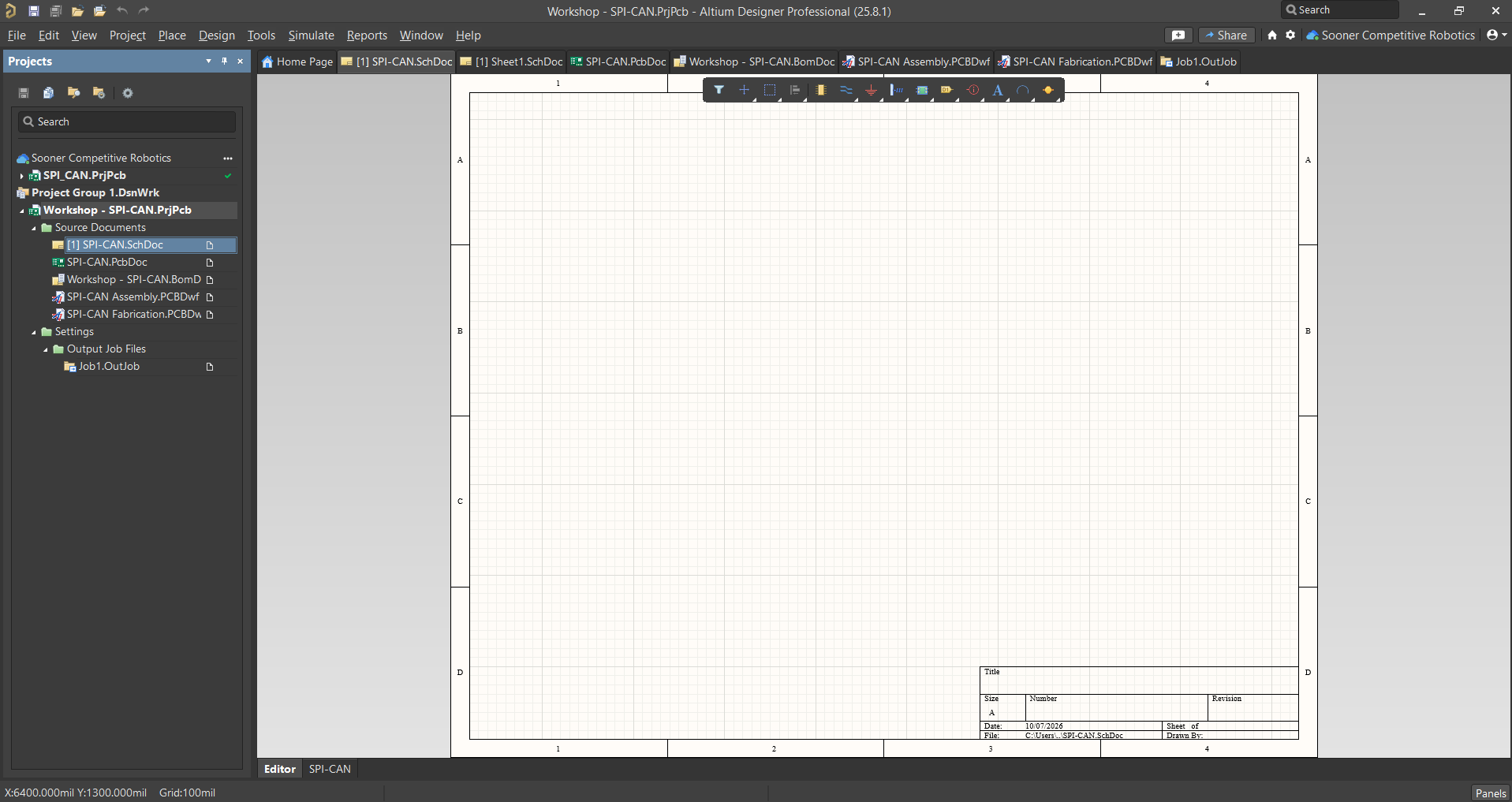
Before designing your circuit schematic, it's important to make sure your sheet has everything set-up properly. This includes the Sheet size, title, author, and more.
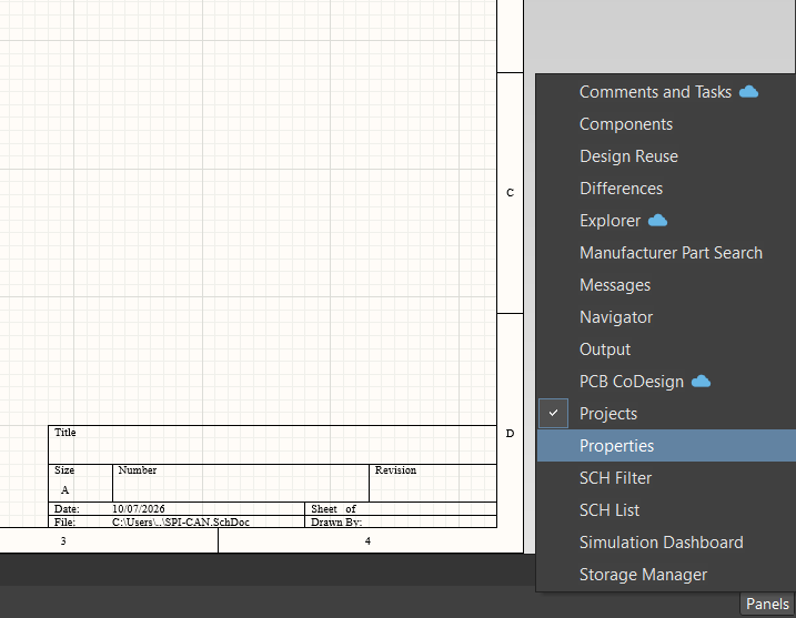
A new window should appear as seen below:
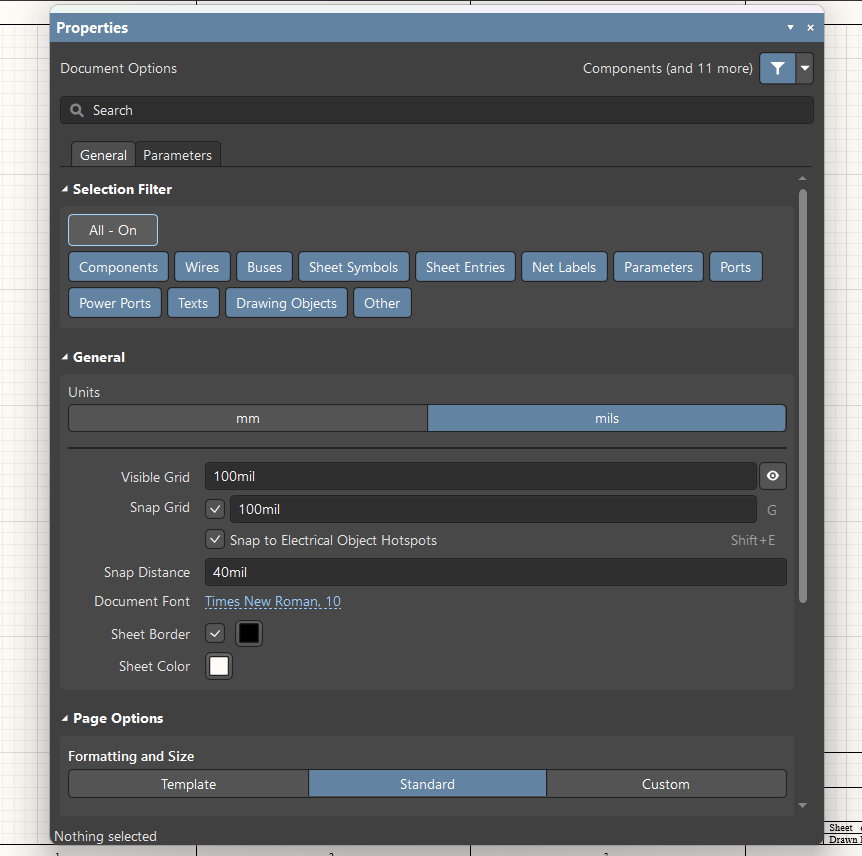
You can